
In this article, we’ll be taking a look at potentiometers. But before we begin, let us do a quick revision on resistors.
We learned in the previous tutorial that a resistor is a two-terminal device that restricts the flow of electrical current when a voltage is applied across the two terminals. The resistance is a measure of how strongly the resistor opposes electric current and is measured in ohms. The value of the resistance determines how much current flows, depending on the voltage applied to the two terminals. This can be calculated using Ohm’s law: I=V/R.
Now, imagine there’s a way to add a third terminal to the resistor that can be moved around. The third terminal, known as the wiper, is moved around in order to change the resistance. Adding this third terminal converts the resistor into a potentiometer. By this, we can say that a potentiometer is essentially a resistor that has a mechanical adjustment that lets you manually change the resistance.
We can then define a potentiometer (also known as a pot or potmeter) as a 3-terminal variable resistor or voltage divider (a network of resistors that is used to reduce the voltage by some factor) in which the resistance is manually varied to control the flow of electric current.
Potentiometer Construction
Potentiometers consist of three main components: a resistive element, the wiper, and three terminals.
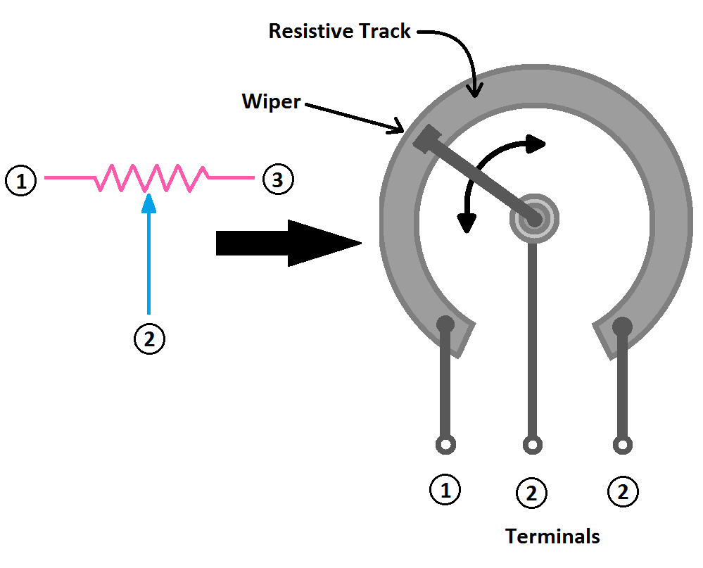
The resistive element is often graphite, though other common materials include resistance wire, carbon particles in plastic, and a ceramic/metal mixture called cermet. The above circular track is for a rotary potentiometer (don’t worry, we’ll get to the types of potentiometers). In a linear potentiometer, the track would be a straight line as opposed to a circular track.
The two outermost connection terminals are wired to the resistive element. These terminals define the total resistance of the potentiometer. Connecting these terminals across a voltage source establishes the full voltage range available for adjustment. They also act as the endpoints of the resistive track, allowing the potentiometer to function as a variable voltage divider. When you adjust the wiper (the middle terminal), it changes the output voltage between the wiper and one of the outer terminals.
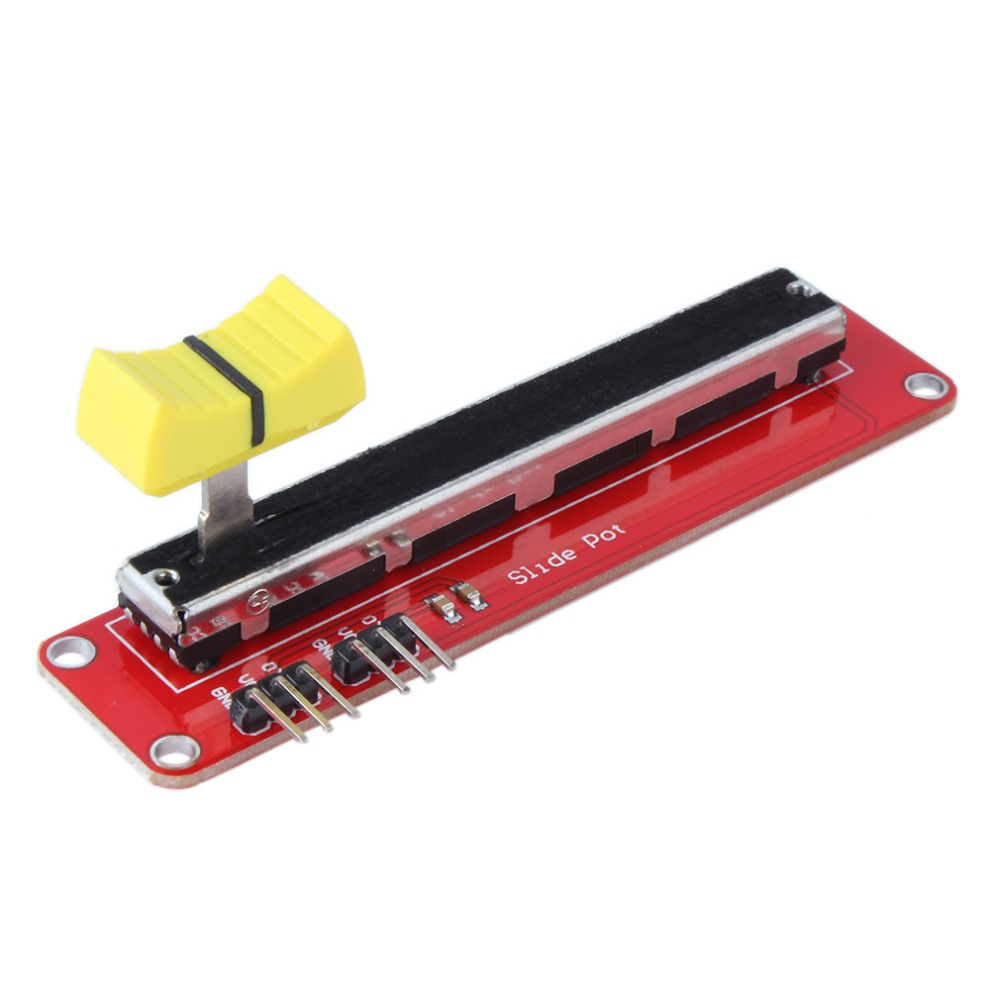
The wiper is the third terminal. It moves over the resistive section of the device, thereby changing the resistance on either side of it. In the case of a rotational potentiometer like the one illustrated above, the wiper is mounted on a pivot point, and it can then be adjusted with a knob or screwdriver. In a slider-style potentiometer, the wiper would sit on a track and behave like the sliders on an audio equalizer.

How a Potentiometer works
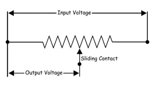
A potentiometer is basically a long piece of uniform wire across which voltage is applied. The basic principle of the potentiometer is that the voltage drop (measure of the difference in voltage between two points in the circuit) across any part of the wire is directly proportional to the length of that section. This principle holds as long as the wire has a uniform cross-sectional area and a constant current flows through it.
Thus, potentiometers work by varying the position of a sliding contact (wiper) across a uniform resistance. A potentiometer has the two terminals of the input source fixed to each end of the resistor. The entire input voltage is applied across the whole length of the resistor (wire), and the output voltage is the voltage drop between the fixed end and sliding contact.
The adjustable output of a potentiometer is achieved by moving a sliding or rotating contact along the uniform resistive element. This action either lengthens or shortens the path through which the current flows. The output voltage is taken from the point between the fixed resistive element and the sliding contact. The position of this sliding contact determines how much of the input voltage is applied to the circuit.
Types of Potentiometers
Analog Potentiometer
An analog potentiometer uses mechanical elements that can be manipulated manually to control the output. There are two main types: linear and rotary.
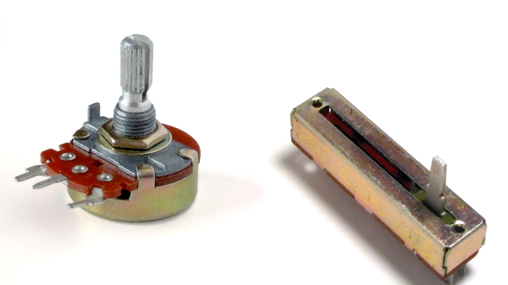
- Linear Potentiometer
With linear potentiometers, the resistance and output are varied linearly in constant steps, depending on the location of the wiper on the resistive component. The terminal connected to the sliding is connected to one end of the output circuit, and one of the terminals of the resistor is connected to the other end of the output circuit.
This type of potentiometer is primarily used to measure the voltage across a circuit branch, measure the internal resistance of a battery cell, compare a battery cell with a standard cell, and, in everyday life, is commonly found in the equalizers of music and sound mixing systems.

- Rotary Potentiometer
Rotary potentiometers use angular movement from a rotating knob and shaft connected to a wiper element that slides across the resistive element. Turning the shaft adjusts the resistance and the output. The voltage is taken between a resistance end contact and the sliding contact.
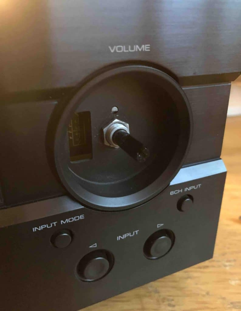
Rotary potentiometers are primarily used to provide adjustable supply voltage in electronic and electrical circuits. A common example is the volume control on a radio, where the rotary knob of the potentiometer regulates the power to the amplifier.

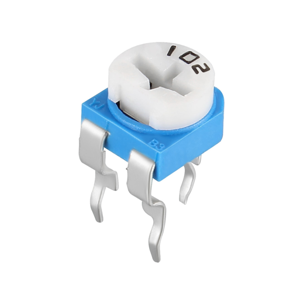
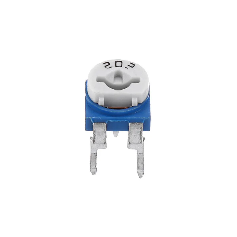
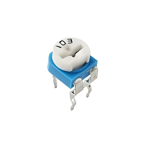
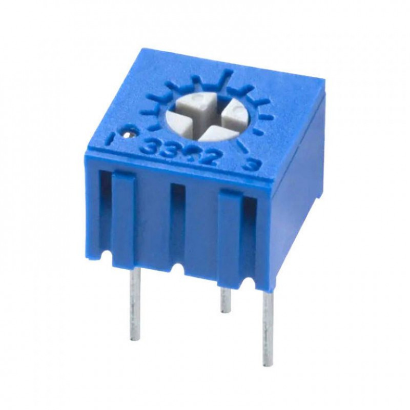
Some rotary potentiometers are shaftless, where an external tool, such as a screwdriver, is used to move the wiper instead of a shaft. These are most commonly called trimmer potentiometers, or trimmers. They are designed for fine adjustments in electronic circuits, often used for calibration and tuning purposes. It is also possible to mount them onto a printed circuit board (PCB) if required.
Digital potentiometers
Digital or electronic potentiometers use digital signals to adjust the output rather than relying on mechanical movement. Digital potentiometers generally offer several advantages over their analog counterparts. Some digital potentiometers are volatile, meaning they reset to a default position when powered off or disconnected. Additionally, digital potentiometers are resistant to shock and vibration, preventing unintended changes in the wiper position, unlike mechanical potentiometers.
Digital potentiometers are used in a variety of applications, such as system calibration, adjusting offset voltage, tuning filters, controlling screen brightness, and regulating sound volume.
That’s all for today, curious minds. Stay tuned for more tutorials and projects.
Until next time, stay inquisitive!


